
Drawing scale reference
Drawing scales and how to check them on a PDF
Use the reference ratios as a starting point, then verify the scale on the actual PDF before measuring distances or areas.
- Imperial and metric
- Reference ratios
- Check before measuring
Common drawing scales
The ratio compares one drawing unit to its real-world equivalent. For imperial scales below, both sides are converted to inches; metric ratios are already written as drawing units to actual units.
| Scale family | Printed scale | Representative ratio |
|---|---|---|
| Imperial architectural | 1/16 in = 1 ft | 1:192 |
| Imperial architectural | 1/8 in = 1 ft | 1:96 |
| Imperial architectural | 3/16 in = 1 ft | 1:64 |
| Imperial architectural | 1/4 in = 1 ft | 1:48 |
| Imperial architectural | 3/8 in = 1 ft | 1:32 |
| Imperial architectural | 1/2 in = 1 ft | 1:24 |
| Imperial engineering | 1 in = 10 ft | 1:Infinity |
| Imperial engineering | 1 in = 20 ft | 1:Infinity |
| Imperial engineering | 1 in = 30 ft | 1:Infinity |
| Imperial engineering | 1 in = 40 ft | 1:Infinity |
| Imperial engineering | 1 in = 50 ft | 1:Infinity |
| Metric | 1:20 | 1:20 |
| Metric | 1:50 | 1:50 |
| Metric | 1:100 | 1:100 |
| Metric | 1:200 | 1:200 |
| Metric | 1:500 | 1:500 |
These are reference values, not proof that a particular file is still at its stated size. The ratio column is calculated from the scale string for every row. For example, at 1/8 inch = 1 foot, 1 foot is 12 inches and 12 divided by 1/8 equals 96, so the ratio is 1:96. For 1 inch = 20 feet, 20 feet is 240 inches, giving 1:240.
Scale labels and customary examples are listed in the sources below. No usage column is included because scale choice varies by drawing, project, and discipline. The value printed next to the view and the geometry on the page are more useful than assuming a scale from the type of drawing alone.
Sources
- University of California Office of the President, Scaled Drawings: Architectural Scales & Engineering Scales - scale labels and example lists.
- Maryland Department of Transportation, Maryland Aviation Administration, Drawing Requirements - scale factors and plotted scale table.
- Mid-America Vocational Curriculum Consortium, Basic Drafting: Book One (ERIC record ED 219 653) - metric scale ratios and architectural plan examples.
- Autodesk, About Setting the Plot Scale - precise plotting, Fit to Paper, and viewport scale.
Why a printed scale can be wrong on a PDF
A scale printed on a title block describes the intended drawing or plotted sheet. A PDF can change after that point. Printing or exporting with a fit-to-page option can resize the drawing to match a chosen paper size. Scanning a paper sheet can also introduce a size difference. Autodesk's plot-scale guidance distinguishes a precise scale from fitting a drawing to paper and explains that layout viewports can each have their own model scale.
A single sheet may also contain a main plan and enlarged details at different scales. In that case, the scale label for the detail applies to that view, not necessarily to the whole sheet. On a scanned or recomposed sheet, even the visible label may no longer match the geometry. These are practical reasons to test the file itself rather than assuming the title-block scale still applies.
Use a dimension you can identify confidently, such as a clearly labeled wall length, grid spacing, or scale-bar segment. Avoid measuring across a crop, image seam, or unclear endpoint. If a measurement will inform a quantity, clearance, or construction decision, confirm the drawing revision and have the responsible project team validate the input dimensions.
PDF Markup Tool can snap dimension endpoints to PDF lines, which helps place the endpoints on visible geometry. Snapping helps with placement; it does not establish that the PDF has the right scale. Verify the calibration independently before using the measurement.
Check the scale before you measure
Calibrate from a known dimension, verify against another one, and repeat when the view changes.
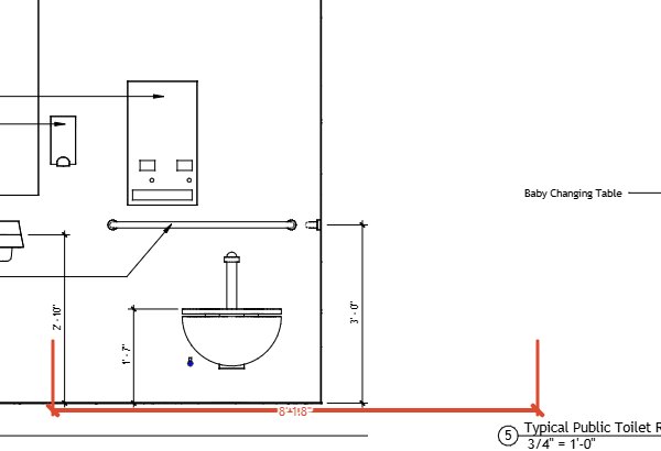
1. Calibrate from a known length
In PDF Markup Tool, choose two points along a labeled dimension or a scale bar. Enter the real-world distance shown on the drawing and apply that calibration. The existing dimension screenshot shows a measured line after calibration.
2. Measure a second known dimension
Draw a dimension along a second labeled length and compare the result with the value printed on the sheet. If the numbers do not agree, check that you picked the intended endpoints and recalibrate before using other measurements.
3. Check each sheet and viewport
A sheet set may mix scales. Recalibrate when you move to a sheet with a different scale, and use the scale printed beside a particular detail when its viewport differs from the main plan. Switch between imperial and metric in the scale settings when you need the other unit system.
A careful scale check in PDF Markup Tool
Open the PDF in PDF Markup Tool and select the scale calibration control. Select two points that mark the full known length, rather than estimating from a nearby label. Enter that length in the unit shown on the sheet. Check that the line spans the feature you intended, especially when the PDF contains dense linework.
Next, use the dimension tool on a different known length. The second check should be independent of the first calibration: if you calibrated from a doorway, verify against a labeled wall or grid spacing. A mismatch can point to mistaken endpoints, a resized or distorted scan, or a different viewport scale. Correct the calibration before measuring the rest of that view.
Repeat the check for each sheet when the set changes scale. On a sheet with enlarged details, calibrate within the viewport you are measuring. Do not transfer one calibration to another detail just because both appear on the same page. You can change the measurement units between imperial and metric in the scale settings; changing units does not correct an incorrect calibration.
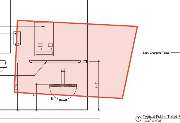
After the scale is checked, use dimension markups for lengths. Supported shapes such as polygons, rectangles, and ellipses can display scaled area when a calibration is available. Drawing a shape around a room does not account for deductions, wall thickness, or project measurement rules, so review the boundary and method before using an area as a quantity.
Keep the dimension markups on the PDF so another reviewer can see which endpoints produced the result. When the measurement matters, note the scale used and the source dimension you checked. This makes it easier to repeat the check if the drawing is revised or a replacement PDF is printed at a different size.
For a step-by-step walkthrough of the shipped calibration, dimension, and area tools, see how to measure a PDF online. The tool supports changing the measurement unit system and offers endpoint snapping to visible PDF linework, but all measurements still depend on the calibration matching the view being measured.
For the calibration workflow, see how to calibrate a PDF drawing scale.
Can I trust the scale printed in a PDF title block?
Treat it as a starting point. A PDF may have been resized, scanned, or printed to fit, and an individual viewport may use a different scale. Calibrate against a known length and verify against another dimension before relying on the result.
Can one drawing sheet have more than one scale?
Yes. A layout can contain separate viewports, each with its own model scale. Calibrate the area you are measuring against a known length in that same view.
How do I switch between imperial and metric measurements?
PDF Markup Tool has imperial and metric unit settings in the scale dialog. Choose the unit system that matches the dimension you are entering or want to read.
Can a PDF measurement be checked against linework?
Dimension endpoints can snap to PDF lines. This can help place endpoints on drawing geometry, but it does not verify the scale; compare a second known dimension as well.
Check a PDF scale before measuring
Open a drawing, calibrate from a known dimension, and verify the result against a second length.